The Warm Heart Flame Cap Trough
by Karl J. Frogner, PhD
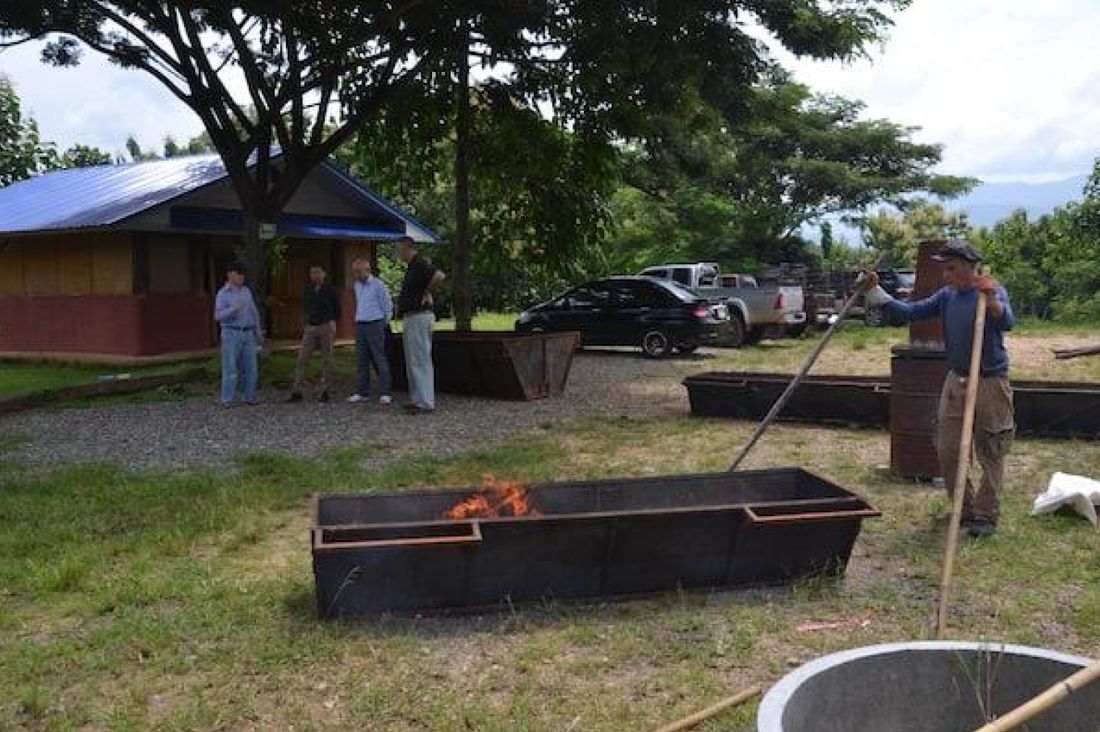
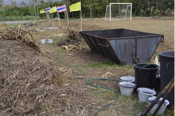
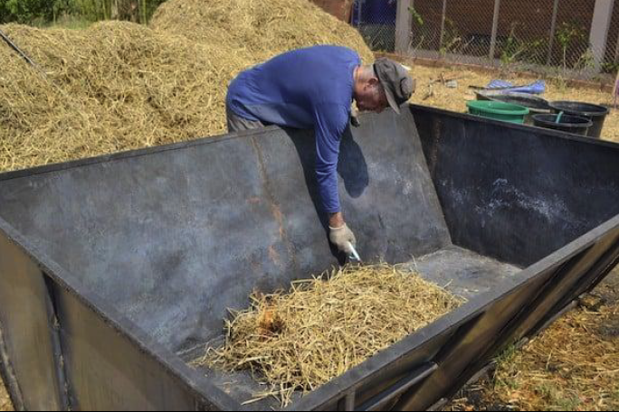
A flame cap trough biochar production unit has been developed by the Warm Heart team. These Flame Cap Trough units, which are defined as above ground FC units with a non-square, rectangular top aspect.
The general design was developed as a result of considering the easiest low tech way to pyrolyze a great variety of the feedstock types available to the small farm holders in developing countries, that is, with a minimum amount of processing &/or transportation of the feedstock beyond the initial harvesting.
Given this economy of effort/cost and the basic growth pattern of much potential feedstock, the design will be of interest to the small to medium low tech, distributed biochar makers in developed regions. These are derivatives of the original Japanese technology and are Top Fed Open Draft FC units and not to be confused with kilns since they do not fit the Standard English definition of kiln.
The Warm Heart team took the basic Flame Cap trough concept and, with the support of management, come up with a special FC Trough design which features reduced weight without sacrificing durability and without greatly increasing fabrication cost or difficulty.
This is accomplished by reducing the thickness of the firebox sheet metal and laying out the base and long sides as a single rectangular panel so that the sides are simply bent up from the central base section of the panel at the desired angle.
The ends are inverted isosceles trapezoids congruent with the outline of the bent base and long sides. They are welded on at right angles to the base. This lightweight fire box is cradled in a light weight supporting frame made of box iron (or square iron – iron bars with a hollow square cross section).
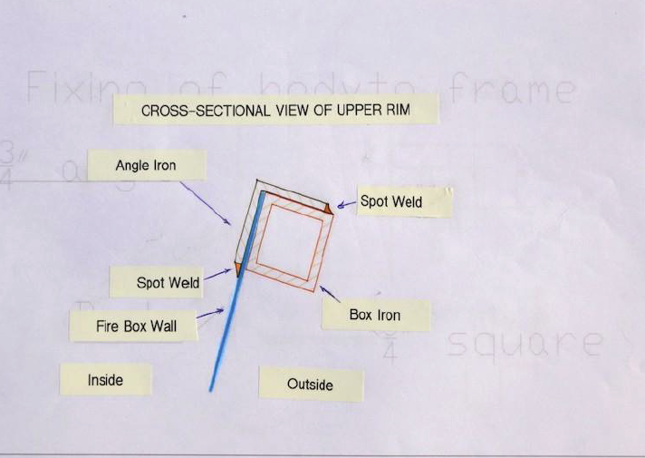
To further strengthen the unit and secure the firebox in place, four angle irons encircle the top of the unit with the downward facing arms on the inside of the unit and the opposite arms making the uppermost rim of the unit. Thus the firebox rim is sandwiched between the box iron cradle rim and the angle iron (See schematic details, photos 22 &23)
This basic concept will be referred to as the Warm Heart Trough design.
2) The WH T 500 oven – This 500 l oven trough was specifically designed for hill tribe
farmers for 2 person distance carry on steep, rough, and/or forested terrain either by
using a carrying pole or the alternate side handles, front & back. The extra-long
handles allow for up to 8 persons to carry the unit when carrying a load. It is also
small enough to be easily moved by one person on level ground, in a cart, or with a
set of strap on wheels.
3) The original Flame Cap Trough (WH T 2k) – This is the first version of the 2 cu. m.
LLU (large low-tech unit) trough. It was designed to sit on top of a towing skid which
raised the angled sides enough to clear the wheel wells of the small pickup used for
transportation. Towing in the rough local fields proved difficult and the local workers
preferred to hand carry the unit. Foregoing the towing skid resulted in the sides
coming in contact with the wheel wells before the bottom of the unit rested on the
truck bed so the profile was made narrower at the base and taller in the standard
design. The handles extending from the top of the original design made lifting the unit
for ground clearance when hand carrying somewhat difficult for all but tall individuals.
This would have been accentuated by the added height of the second rendition, so
the handles were lowered to the sides in the standard version and lengthened so that
two persons could carry in tandem at each handle for added lifting power. Also, local
workers preferred to bucket or tip excess water out of the units. Consequently, the
drains were seldom used and usually allowed to rust shut, so few of the other units
were fitted with them to save on unit cost and fabrication effort.
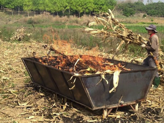
The man stoking the unit in the photo is a member of a 6 person team, 5 of whom cut
and carried the cornstock to the unit with the sixth stoking. The stoking position was
rotated amongst all the members during the run. Each team uses 3 T 2k units in the
standard charring procedure developed locally. These units are placed at strategic
positions in the field to minimize feedstock carrying. Each unit is filled with char and
quenched in succession and after lunch the char is bagged.
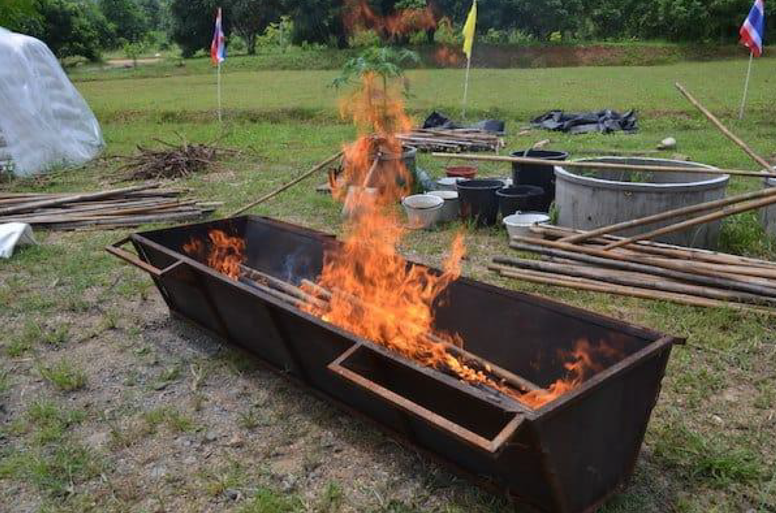
4) The standard Flame Cap Trough (WH T 2k) – This is the evolved 2 cu. m. LLU
trough. It is the workhorse of the Warm Heart line, proving itself suited for major
distributed low-tech biochar production in small farmers’ fields and forests, utilizing
cornstock, rice straw, fruit tree prunings or bamboo. Pictured here is the beginning of
a successful test with mixed feedstock consisting of (to the rear of the unit) corn husk
and fruit tree prunings, and (left foreground) lemon grass, and behind that cornstock.
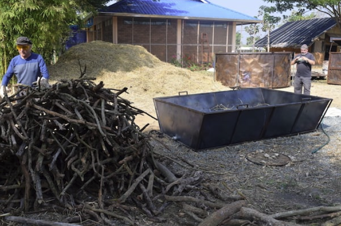
5) A pile of fruit tree trimmings to be charred in a Flame Cap Trough (T 2k). Warm Heart Engineer Gordon Hirst, responsible for developing the concept of thelightweight but strong firebox and box iron cradle, is seen in the background photographing the unit.
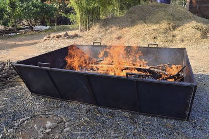
6) Fruit tree trimmings charring in a T 2k. The 2.3m length easily accommodates almost all fruit tree trimmings while the standard T 2k’s 1.6 m top width means it can handle most all of the branchy trimmings without additional processing.
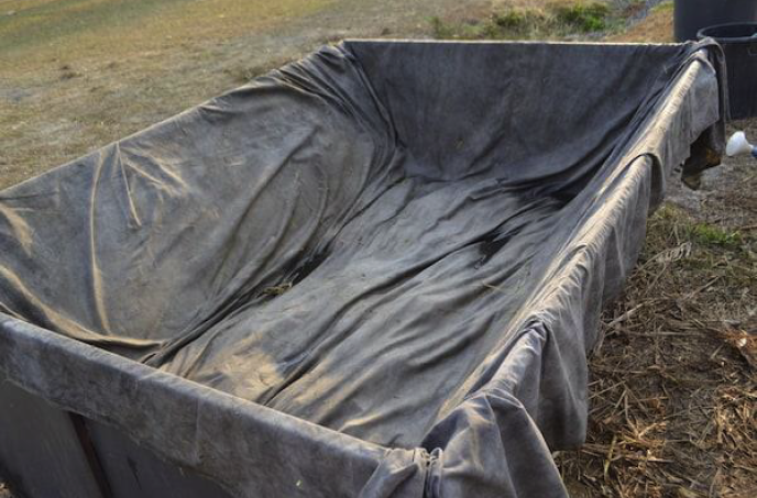
7) The wet blanket snuff. In areas where water is scarce or difficult to transport in, the water needed can be greatly minimized by a first light quench of the top hot coals followed by covering the char and unit sides with a water soaked heavy canvas blanket.
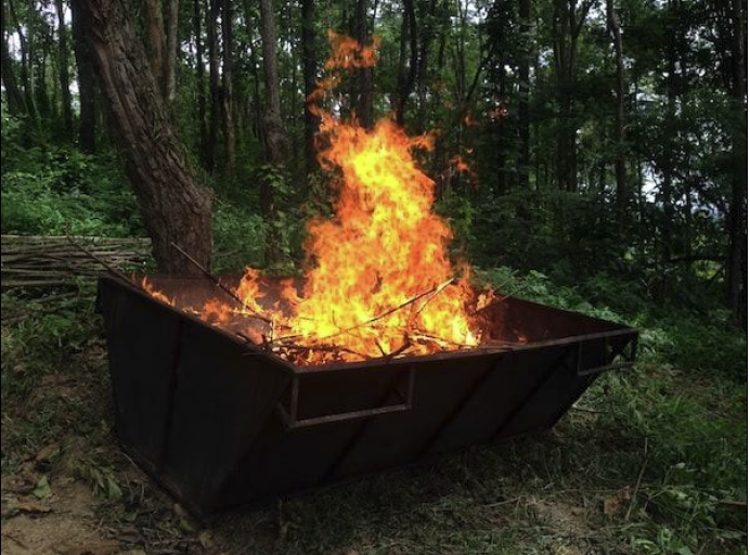
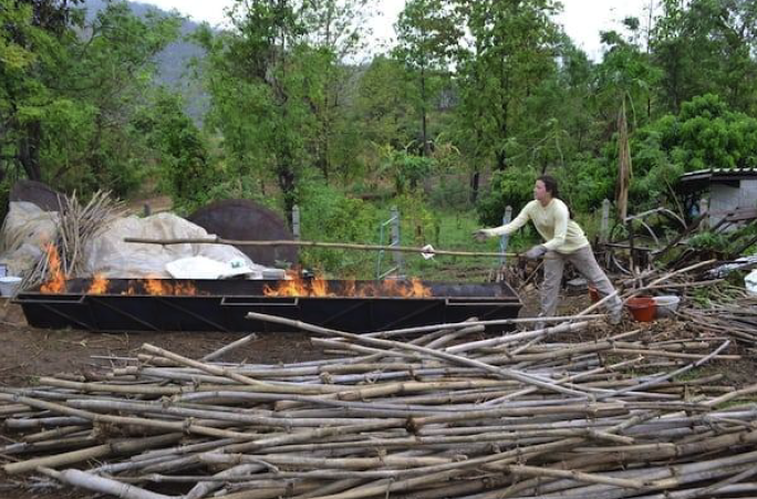
8) Charing bamboo feedstock in a standard Flame Cap Trough (WH T 2k LLU) on site in a forest setting. Light branches are burning to build a bed of hot coals for larger lengths in the background.
9) The resulting char load. The resulting bamboo feedstock char has been heaped in one end to facilitate finding hot spots and to expose the unit’s water table so the earlier quench water can be reused on hot spots. In addition, this allows soaked char to drain. Such strategies lessen the quench water needed even if a wet snuff blanket is not used.
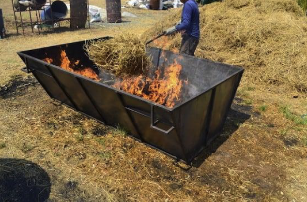
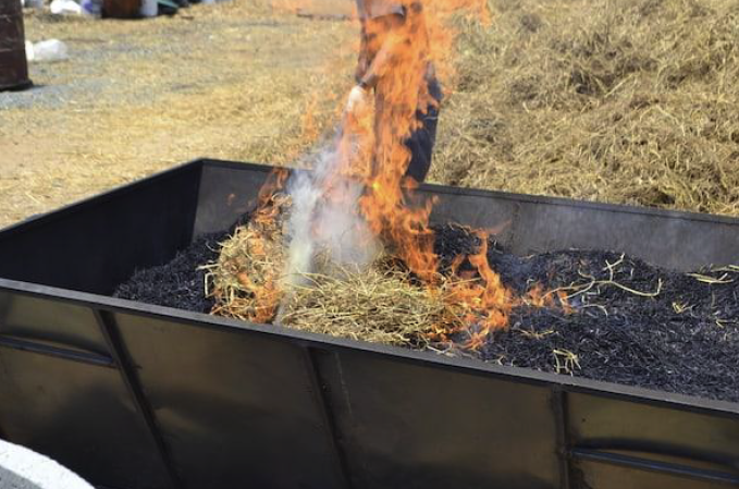
10) The Flame Cap Trough (WH T 2k LLU) can also produce char from rice straw without smoke pollution. The burn is started by lighting a small pile of rice straw in the center of the unit.
10) The Flame Cap Trough (WH T 2k LLU) can also produce char from rice straw without smoke pollution. The burn is started by lighting a small pile of rice straw in the center of the unit.
11) Early straw stoking – spreading the fire. Straw is added with the aid of a long metal handled pitch fork, placing one forkful at a time in very quick succession.
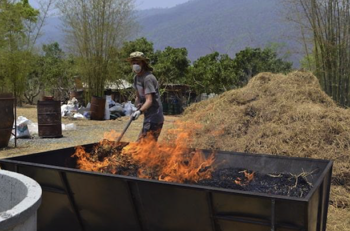
12) Rice straw – drag stoking. Several methods of stoking were developed to allow clean, smokeless charring without excessive ashing of the straw. One of these methods consisted of dragging a forkful of straw along the surface of the char load to deposit a burning band of new straw and resulting char.
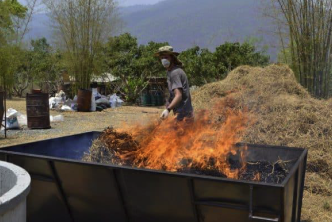
13) Roll stoking rice straw. Another stoking method consisted of rolling the forkful of straw along the surface until the outside of the ball was aflame and then depositing the flaming ball where desired. The flames on the outside of the ball consumed the smoke generated by the igniting straw inside.
14) Pit stoking in late burn. A third method of stoking that can be employed after a deep bed of char has been built up is to rake a pit in one section of the trough and deposit balls of flaming char in it until it is filled with char, then move to the next section of the trough and repeat. Note the smoke being generated by the igniting straw being burned as it is sucked up the flaming updraft.
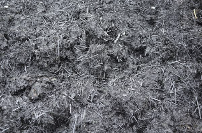
15) Rice straw char. A cross-section of the char load as it is being bagged a shovelful at a time with an eye out for hot spots.
16) Stoking the Flame Cap Trough (WH XLT 1k) with long bamboo. The XLT is a 1 cu. m. LLU trough. Its length (4.7m) was specifically designed for bamboo feedstock to minimize the time, effort, and expense of cutting. The same calculus should hold for pole pine and coppiced wood. Note the placement of the 3 long handles on the side, thus allowing for up to a 12 person carry for heavy loads. The basic construction weight is approximately the same as the T 2k and so can be carried empty by 4 individuals.
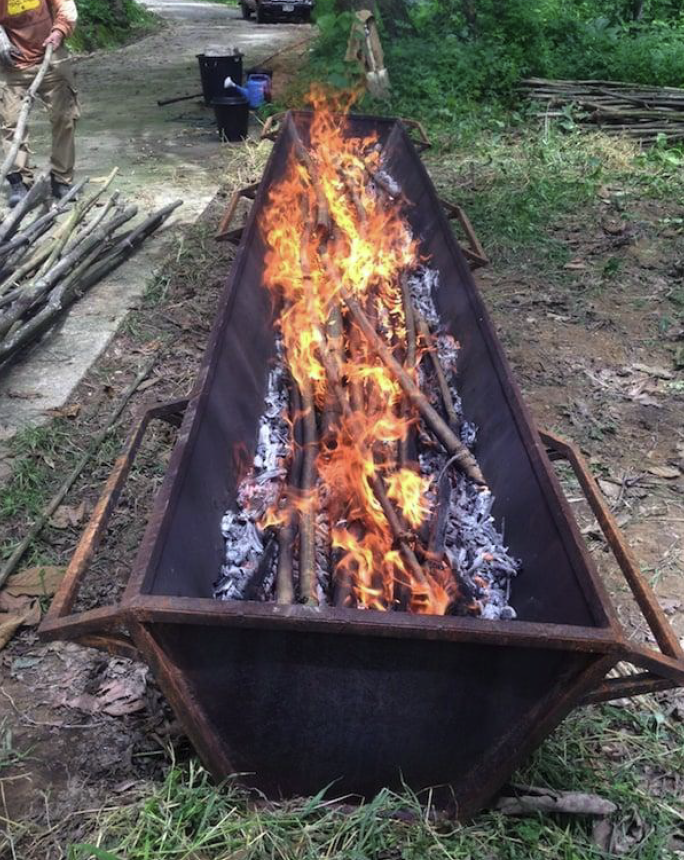
17) XLT 1k – Long view with fire in the box. Note the detail of the long handles
18) XLT 1k with a load of bamboo char
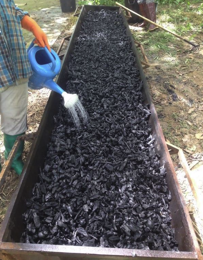
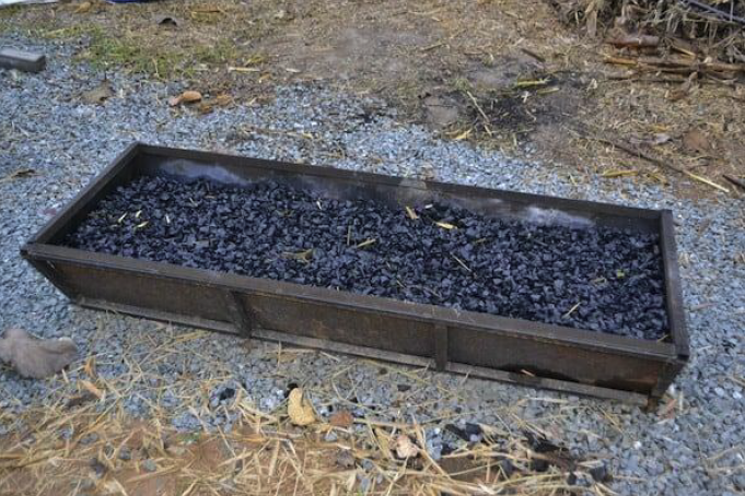
21) Flame Cap Trough (T 200 oven). This is the original test unit for the Flame Cap Trough concept in general and sized for comparison tests with the UB JRO 200 l TLUD oven design. It showed conclusively that the two were complimentary at equivalent size. If the feedstock is of appropriate size, the ‘light and leave’ characteristic of the JRO has the advantage over the ‘light and attend’ FC units since the small scale distributed producer can attend to other matters during the burn and, aside from some simple loading principles, does not have to master stoking skills. In addition, with the right kind of feedstock, the inherent product of the JRO is more uniform and likely to be of a higher porosity. On the other hand, the Flame Cap trough has a much greater range of acceptable feedstock types without additional processing, a greater bulk char production potential for a given sized unit and the basic design is very flexible and easily sized up to handle feedstock abundance and inherent dimensionality.
The basic stoking skills are not that difficult to learn with a bit of practice with the various classes and conditions of the potential feedstock. The tree trimming char shown here in the unit resulted from the burn of the tree trimming feedstock pictured in photo 20. This unit is on indefinite loan to an up-scale hotel in Chiang Mai to process their grounds trimmings, etc. into char for recycling in their composting program, part of the local anti-smoke pollution program.
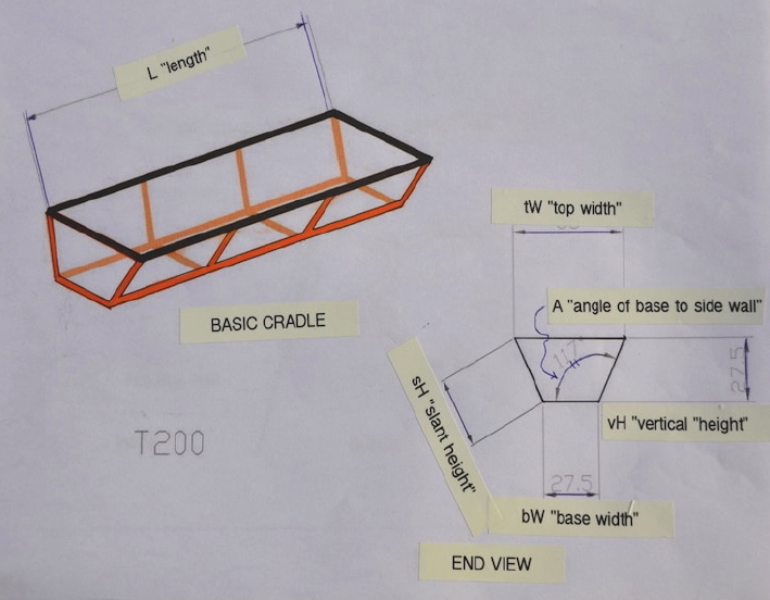
22) Generalized schematic of WH flame cap trough. See table of standard dimensions and photos for added details of particular units.
22) Generalized schematic of WH flame cap trough. See table of standard dimensions and photos for added details of particular units.
23) Cross-sectional view of upper rim. The spot welds are made at rough intervals of 12 to 18 cm around the rim with the series of welds of angle iron to box iron and angle iron to fire box being offset from each other.
Standard dimensions for the 4 Flame Cap Trough units currently in the Warm Heart line:
T 200 oven
Base width (bW) ~ 28 cm
Top width (tW) ~ 55 cm
Vertical height (vH) ~ 27 cm
Slant height (sH) ~ 30 cm
Length (L) ~ 170 cm
Volume (V) = 190,485 cc ~> 200 l = 0.2 cu m.
Inside angle iA ~ 117°
T 500 oven
Base width (bW) ~ 28 cm
Top width (tW) ~ 64 cm
Vertical height (vH) ~ 43 cm
Slant height (sH) ~ 47 cm
Length (L) ~ 243 cm
Volume (V) = 480,654 cc ~> 500 l = 0.5 cu m.
Inside angle (iA) ~ 113°
XLT 1k LLU
Base width (bW) ~ 32 cm
Top width (tW) ~ 67 cm
Vertical height (vH) ~ 42 cm
Slant height (sH) ~ 45 cm
Length (L) ~ 473 cm
Volume (V) = 983,377 cm3 ~> 1k l = 1 3 cu m
FORMULAS:
Volume: V = (bW+(tW-bW)/2) x vH x L
Slant height: sH = short dimension of the rectangular panels making up the
long walls of the unit (see photo 22).
Inside Angle: iA = base to slant wall (labeled A in photo 22) = Acsgnet° + 90°;
where Acsgnet° is determined from
http://www.csgnetwork.com/righttricalc.html using measured ‘c’ {= sH} & ‘a’ {=
(tW-bW)/2}
Depression Angle: dA = 180° – iA

